How to Develop F0-based Sterilization Cycle?
Once the concept of the F0 value is clear, next step is to try out practical application by developing an automated cycle.
The automation industry is rapidly growing now. Life-sciences too are fastly adapting to the automation to avoid the audit observations.
Steam sterilization is no exception to this. In the manual days, steam sterilization was impacted by inconsistent SAL values.
Temperature control was a major concern. Audit findings regarding the sterility of the finished drugs also raised questions about SIP authenticity.
Eventually, automating the sterilization cycles made it manageable.
As of now, the following are the two fundamental types of steam sterilization that are commonly used in the pharmaceutical industry.
Table of Content
Sterilization Categories
- Sterilization Out of Place e.g. Autoclave (loose components or pieces that can’t be sterilized at their designated place)
- Sterilization in Place (SIP) e.g. SS Process Vessel (systems that aren’t mobile)
Ultimately, they deal with the same thing, “Reduction of micro-organisms to their predetermined acceptable levels“.
For this to happen, systems undergoing sterilization should maintain uniform temperature distribution throughout the cycle. Ultimately, the drug makers have to assure their product’s sterility, safety, and quality.
To develop a steam sterilization cycle, let us illustrate the 2nd one i.e. Sterilization In Place (SIP).
Consideration
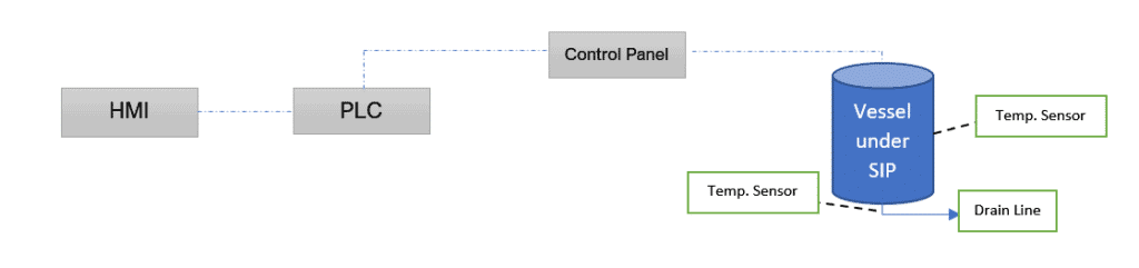
Consider a SS vessel under steam sterilization having multiple temperature sensors. The key point in any sterilization is realizing when to stop.
To make it simple, we’ll consider two sensors, one in the vessel shell (nearest) and one in the drain line (farthest). The figure below depicts the sterilization using a controller.
Steam Sterilization Cycle Development
At present, the following are the conditions to automatically terminate the sterilization:
1. Time-based (Cycle ends once the sterilization timer ends)
2. F0 value-based (Cycle ends once F0 value is achieved)
We’ll see one by one.
Time Based Sterilization Cycle
Any automated sequence runs on the basis of pre-defined recipe parameters.
So, here are the recipe parameters that will be displayed on an HMI screen.
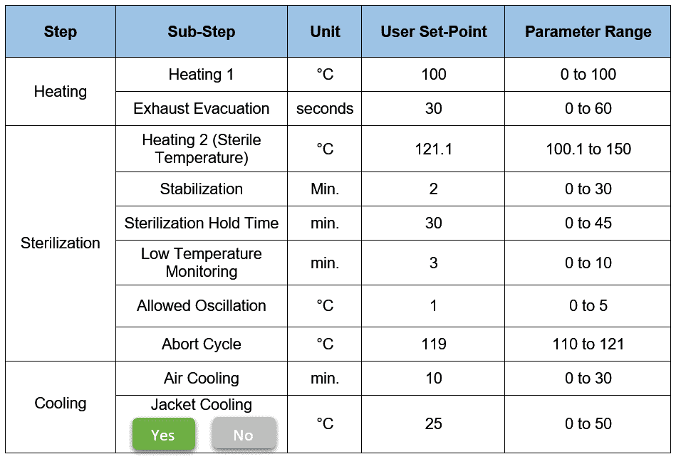
You see, there are three main steps here: Heating, Sterilization, and Cooling.
Let’s break down.
Heating
The steam inlet valve opens to introduce the steam into the system.
Heating 1 heats the system to a certain temperature typically up to 100°C to attain a proper temperature distribution across the system.
When it reaches the Heating 1 set point, the exhaust evacuation set point timer starts. This step eliminates air pockets by pulsing (ON/OFF) the exhaust line valves.
Note: Removing the air is essential for effective sterilization because it insulates and obstructs steam penetration.
Valves get closed when the timer is complete.
Though the set-point triggers, the system still needs to be stabilized before sterilization.
Stabilization
In the sterilization phase, the stabilization step begins with the Heating 2 setpoint (in our case, it’s 121.1°C).
Once the lowest temperature sensor achieves the “Temperature SP – (minus) Oscillation SP”, the controller triggers the stabilization. Meaning, the system is stabilizing for the sterilization temperature.
Stabilization helps to attain a consistent temperature profile with the help of a steam inlet valve that pulses (ON/OFF) based on feedback values.
For stabilization, the coldest (worst) temperature sensor in the system drives the transition steps. Thus once the coldest temperature sensor enters the acceptable range, the stabilization timer activates. These sensors update in real-time based on steam flow and logic.
Once the stabilization timer ends, the system moves to the sterilization step.
Sterilization
As per our recipe, Sterilization Hold Time is set as 30 minutes. Allowed Oscillation entered as 1°C. This implies the acceptable sterile temperature range is between 120.1°C to 122.1°C.
After stabilization, if all the temperature sensors are within the acceptable range, the sterilization starts and completes after 30 mins.
But, if any of the sensors during sterile hold go below the lower acceptable value, the sterilization hold timer pauses. PLC then triggers “Low Temperature Monitoring Timer” (in our case, it’s 3 min.).
During this time:
- Steam inlet valves are kept open to allow continuous steam inside the system
- PLC checks for temperature sensor/s whether attain their acceptable range or not
- If YES, the sterilization hold timer resumes/restarts (see note), and sterilization then ends after the remaining hold time.
Note: Some drug manufacturers restart the timer because they want to ensure once-through steam penetration for the complete hold time without any interruption. But, some resumes too. - If NO, sterilization fails, and the system transits to the Cooling phase.
- If YES, the sterilization hold timer resumes/restarts (see note), and sterilization then ends after the remaining hold time.
If at any moment during the stabilization and sterilization, any of the temperature sensors hit the Abort Cycle setpoint (in our case, it’s 119°C), the cycle fails and transits to the Cooling phase.
Cooling
As the sterilization sequence has succeeded, failed, or aborted, the next phase is “Cooling”.
Generally speaking, there are two ways to cool the system:
- Air cooling: By introducing process-grade air directly into the system
- Jacket cooling (optional): By introducing the chilling media in the jacket.
Air Cooling
Air cooling serves the following purpose:
- Reduces the temperature of the system
- Helps to remove the condensate in the system
In this, process-grade air is introduced through the steam flow path ensuring complete condensate removal.
The system should not be over-pressurized amid air cooling. For that, the pressure transmitter gives feedback to the PLC to maintain the pressure. PLC opens or closes the air supply valve accordingly.
Hot process-grade air (~75-80°C) is also sometimes preferred for cooling enabling more effective condensate removal.
Jacket Cooling
Jacket cooling is employed when the system requires cooling at even lower temperatures.
Lowering the temperature also reduces the pressure and may create a vacuum in the system. To avoid this, the vessel pressure is maintained in a similar fashion to air cooling.
Calculating and Printing F0 Value on Sterilization Report of Time-Based Sequence
Either you go with a time-based or F0-based cycle, the F0 value is an important indicator.
Though being a time-based cycle, PLC can calculate and print the F0 value on the executed sequence report through SQL (Standardized Query Language).
As per the defined print intervals, SQL logs data from the PLC database in a required format. This data is then processed simultaneously until the cycle completes.
Calculations of the F0 value can be done by the controller using a pre-written formula in the logic. The F0 value may get digitally printed on the report.
Despite time-based steam sterilization, the calculated F0 value is useful for future investigations, analyses, and interpretations. For example, testing success rates of the cycle.
So, that’s all about Time Based Sterilization.
Now, let us refresh our approach for F0 Based Sterilization Cycle.
F0 Based Sterilization Cycle
Consider the same recipe parameters as previously mentioned. Just replace the “Sterilization Hold Time” with “F0 value” in minutes.
Moreover, the abort conditions mentioned in the recipe becomes invalid here because the temperature fluctuations automatically get adjusted for lethal doses during sterilization and associated F0 value calculations.
For this cycle, consider the F0 value setpoint as 30 minutes. Here, the calculation part plays an important role in effectively controlling the sterilization cycle.
Note: F0 calculation can either start from Heating 1 or from Heating 2 till Sterilization ends. Some prefer only Heating as a single-step rather than dividing it into Heating 1 and Heating 2 based on their preference and system suitability.
There are many ways to do the F0 value calculations through PLC. The most common ones are:
- Upon completion of the sterilization cycle, PLC calculates the average F0 value from each probe. Therefore, bracketing between sterilization start and end times is practiced to get a meaningful outcome. OR
- Calculate the individual lethal rate for each time interval for each temperature probe and then calculate the individual F0 value for that time interval. Likewise, follow the same pattern for other probes. Once all the probes have their final F0 value, then averaging them would result in the final F0 value. OR
- Calculate the lethal rate for each probe. Average it. And then calculate the F0 value.
Either way, the final F0 value is bound to give slight variations. To keep things simple, we’ll stick with the 1st way.
As seen in the above recipe, “Allowed Oscillation” is set as 1°C.
- If the F0 value calculated from 1°C lower than the coldest (worst) temperature sensor entering the sterilization set temperature, the lethal doses get accounted for the F0 (minutes) setpoint, i.e. only sterilization phase.
- If F0 calculated from 100°C for the coldest (worst) temperature sensor entering the Sterilization set temperature, the lethal doses get accounted for Heating 1 + Sterilization + Cooling phase.
These doses are taken into account to determine the successful termination of the sterilization phase.
Professional practitioners consider the 1st case as a sound practice for sterilization of hard or porous material. Whereas, the 2nd case is recommended when dealing with heat-sensitive materials.
Note: To give the F0 value a biological meaning, steam must be in a saturated condition. Neither super-heated nor sub-cooled. Remember, the perfect moisture does the perfect job.
Controlling Sterilization Cycle Using F0 Value
Though Fedegari explains this approach in-depth, let us quickly break down what a PLC may perform in this scenario:
- For every second or less, the PLC takes values from each temperature probe (once the temperature reaches the sterilization temperature setpoint). In our case, two probes.
- It then averages them. Average of each probe over a period of time.
- It uses these values to calculate the imperfect F0 value for each probe.
- It then adds that value to the already gathered F0 value for that probe i.e. expected F0 value.
Briefing the above part,
- Sterilization begins when the lowest (worst) temperature probe reaches the sterilization temperature set point.
- Sterilization end once the lowest temperature probe hits the F0 value setpoint (in our case it’s 30 min).
On an industrial scale, power backup systems are in place to avoid any loss or damage that may occur to product quality. When power failure (3-phase) occurs and the sterilization cycle is in progress, the PLC remains active on UPS (Single Phase).
F0 value in the background is calculated and cross-checked with the preset value.
Note: “3-phase supply failure doesn’t affect sterilization cycle because no 3-phase related movements are directly associated”. But, you may need to check with the indirect ones.
Summary
F0-Based Sterilization cycle is more meaningful than Time-based Sterilization, because of its more practical approach.
This is true for less heat-sensitive material under sterilization.
F0 value calculation is used either for analysis or controlling the sterilization cycle. The ultimate aim is a sterile system.
Potential failures and their control measures are required to be estimated and employed in place.
Safety aspects such as alarms and interlocks should be considered for intimations and avoiding utility mix-up (such as air and steam) respectively.
Conclusion
It is important to consider sound and practical recipe management for the sterilization cycle right at the trial stages including risk assessment and mitigation. Eventually, the micro-organisms must be eliminated to their acceptable limits.
For autoclaves, the control philosophy remains the same with some additional hooks like vacuum pumps, piping modifications, and so on.
Either SIP or an autoclave requires validation prior to conducting commercial runs. We’ll discuss this validation approach sometime later.
If you have anything to share, comment below right now.
According to EMA Decision tree new revision, cycle must be above 121oC for at least 15 minutes, so it is not ok to set 121oC+/-1oC
For calculation of Fo in product, temperature above 110oC (not 100oC) should be taken in account (same EMA document)
You are absolutely right my dear friend. If you read the article carefully, it is step by step demonstration of the recipe parameters which can be set according to the bandwidth of those parameters.
So, in the end, the authorized person who knows recipe setup will create and manage the recipe in compliance with the related regulations.
Can you please write article on TS cycle development based on bioburden?
Thanks, Rajendar having had a great time with Pharma GxP. The TS cycle development is already in the pipeline but delayed due to some other priorities. I urge you to Subscribe to the newsletter so you never miss an update!
On average, how long will it take for the whole cycle of the Recipe (heating till cooling) if I used 10 minutes as sterilization holding time at 121°C?
Hi Surja, actually it depends on many factors like:
– Pure steam quality
– Other recipe set points
– Piping clusters
– System architecture etc.
Due to these dynamics, it’s practically not possible to ideate. I also doubt why you sterilize for 10 minutes at 121°C.
Please share Autoclave validation and Autoclave load pattern validation
Thanks Vishal! It’ll be added as a fresh article soon. Stay tuned 🙂