Effective HVAC System Design for Pharmaceuticals

Having learned about clean rooms and their classification, let’s move on to the design of the HVAC (Heating Ventilation Air Conditioning) system for pharmaceutical industries.
To avoid contamination, cGMP (current Good Manufacturing Practices) requires manufacturing systems to adhere to quality standards. HVAC controls parameters such as Temperature, Relative Humidity, Differential Pressures, and Air Flow for a cleanroom.
cGMP should therefore encompass the selection of MOCs, equipment cascading, personnel movement, and process flow.
Table of Content
HVAC System Design
There are two types of HVAC systems.
- Once-Through (air used in clean room and discarded thereafter)
- Recirculated (it uses air, some parts discarded and some parts re-processed and re-used)
Each of the above two types has its pros and cons tabulated below.
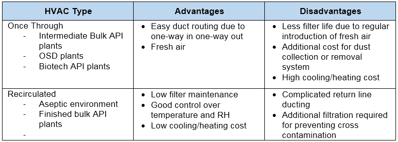
HVAC systems can control various things in an environment including temperature, relative humidity, pressure, airflow, and air quality.
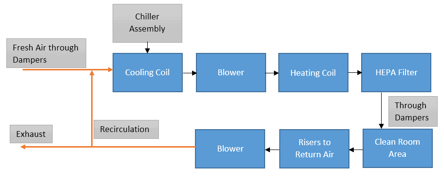
We’ll see one by one. The below diagram represents a general scheme for HVAC systems.
Differential Pressure (∆P) Across The Areas
Differential pressure refers to two areas that are adjacent but maintain different pressures. One area would have more pressure than the other.
The area which comes closer to the cleanroom or itself a cleanroom must be kept under positive pressure than the adjacent area.
This ensures that even if the air-borne particles are present in the adjacent area, they can’t enter the cleanroom as air flows from the higher pressure to the lower pressure area. Air travels through doors across the area. Anyway, we’ll look into this further.
Relative Humidity (RH)
The relative humidity (RH) is the most critical aspect of the HVAC system, and if it is not controlled, it can directly affect the stability and efficacy of the drug product.
HVAC systems can control RH with the help of suitable dehumidifiers. However, there is a difference between Relative and Absolute Humidity.
The actual amount of water vapor present in the air is called Absolute Humidity. While the ratio of the actual amount of water vapor present in the air to the MAXIMUM amount of water vapor the air can hold at that temperature is called Relative Humidity.
Relative Humidity (at defined temperature) = (Actual water vapor in air / Max. water vapor the air can hold)
Absolute Humidity is not practiced commercially as it does not indicate the point of air saturation with moisture and Relative Humidity does exactly that. We’ll discuss this below.
Temperature
In some ways, the temperature is a comfortable parameter for manufacturers to work with. As well as providing comfort to the workers, it prevents the growth of micro-organisms in the work area.
HVAC also controls air-borne particles including dust and micro-organisms with the help of HEPA or ULPA filters. Before detailing this, it is important to know about particulates as they determine the contamination level and its acceptance.
Particulate or Air Borne Particles
Solids present in the air are called Particulates or Air-borne particles. They are very minute in size and measured in microns. Sometimes, these particulates are also called Contaminants or Bacteria based on their structure and biology.
Two potential sources of contamination for clean rooms are mainly external and internal sources.
Cleanrooms are classified into two types.
- Controlled Area (non-sterile application)
- Critical Controlled Area (sterile or aseptic application)
The FDA recommends certain parameters that would help build a quality environment for clean rooms.
Prior to discussing that, let’s see what Air Changes Per Hour (ACPH) means.
Air Changes Per Hour (ACPH)
“Number of times when the total air volume in the room completely removes and replaces in one hour”.
If we remove the air from the room completely once every 60 minutes and replace it with other air, it would mean 1 ACPH has happened.
Below are the FDA recommendations for controlled and critical areas.
| FDA Recommendation | Controlled Area | Critical Area |
|---|---|---|
| Particle count per cubic feet for 0.5µ or higher particle size exposed during activity | ≤ 100,000 | ≤ 100 |
| Bio-burden in CFU (Colony Forming Units) per cubic foot | ≤ 2.5 | ≤ 0.1 |
| Air Changes Per Hour (ACPH) | 20 | Laminar Air Flow: 90 feet/min |
| Differential Pressure in Inch of the water column with closed doors | 0.05 | 0.05 |
Again, there are two types of configurations to design clean rooms based on the pattern of airflow pattern inside the room.
- Multi-directional
- Uni-directional
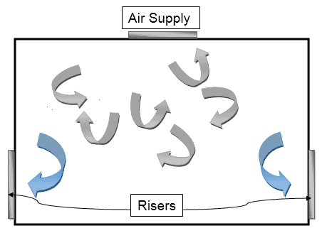
Multi-directional Air Flow Pattern
In this, turbulent air conditions are developed and this turbulent air is typically capable of protecting the atmosphere from external contaminants.
This kind of flow pattern is therefore most commonly seen in Class 10,000 and Class 100,000 where the chances of external contamination are high.
Here’s how it looks like:
Uni-directional Air Flow
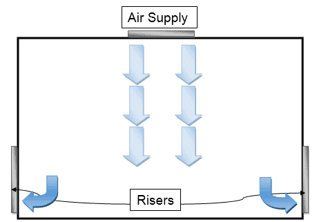
This pattern is useful for low internal contaminants. The flow of air streams in parallel with a single direction is known as uni-directional or laminar airflow with 15 to 20 degrees of deviation.
The parallel direction of airflow occurs either vertically or horizontally based on the application.
In the vertical arrangement, the air is introduced from the top ceiling and returned through walls at the bottom which ensures the airflow pattern is the downside.
In the horizontal arrangement, the air is introduced from one side of the wall and returns through another side which ensures horizontal airflow.
First, i.e., vertical arrangement produces optimum results and is therefore considered frequent.
Design Aspects for HVAC System
Before briefing on the design aspects for HVAC, refer to this flow chart showing the different activities involved during the design of the HVAC system.
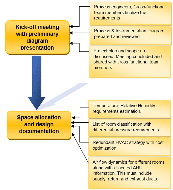
There are various factors that contribute to the efficiency of HVAC such as:
- Specified HVAC requirements, including the room and the system itself. Room includes Temperature, Relative Humidity, Clean Room classification, differential pressure, etc.
- Air Flow Pattern
- Design of ducting
- Building and construction layout
- Heat load
- Location of filtration assembly installation
- Commissioning an HVAC system
- Qualification and Validation documentation
- Releasing the system for commercial applications.
Let us see step-by-step.
Temperature
Concerned with comfort for Personnel, Process, and Equipment, cleanrooms are designed to provide temperatures ranging from 21 to 25°C with a setpoint idea of 23°C.
Sometimes, lower temperature set points are preferred when personnel carries out manufacturing operations with heavy gowns which result in sweat and less comfort. Else, as per process requirements.
Relative Humidity (RH)
Relative Humidity of Not More Than (NMT) 55 ± 5% is mostly preferred in every healthcare industry. However, this much of RH may trouble the areas that handle operations related to hygroscopic (moisture-loving) powders. There, RH should be reduced to 30 ± 5%.
Proper automation would help control the RH and avoid maintenance breakdowns.
If RH is not maintained per the specifications, it may result in:
- Rapid microbial growth
- Metal corrosion
- Personal dis-comfort
- Promoting static charge development
Clean Room Classification
HVAC design is equally concerned with the number of contaminants in the air.
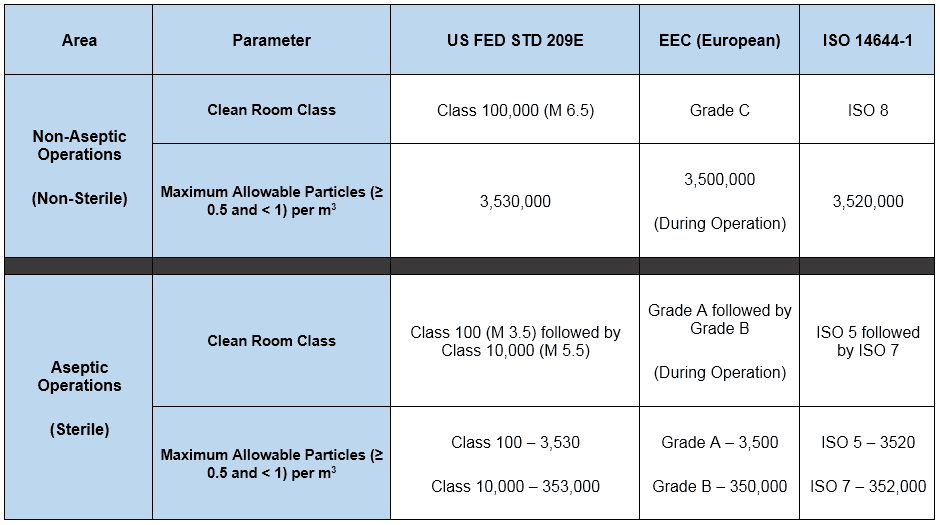
Different FDA recommendations for the classification of cleanrooms were detailed in the table earlier. Now let us see below the summary of the different standards and their requirements.
Differential Pressure (∆P)
As discussed earlier, for the differential pressure across the two areas, one which is cleaner holds more pressure than the other area.
Differential pressure helps to prevent the migration of particles from the less clean area to a more clean area, as air always travels from high pressure to the low-pressure region.
Just like clean rooms, differential pressure also plays an important role in keeping the rooms clean.
The following are the recommended (not requirements though) differential pressures for sterile and non-sterile applications.
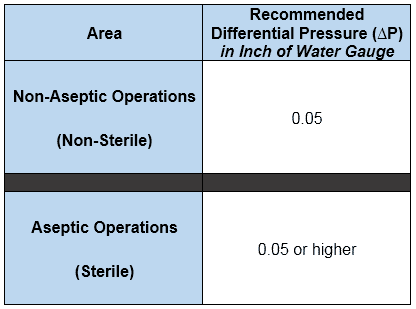
Inch of Water Gauge or Inch of Water Column: It is the pressure exerted by a column of water having 1-inch height.
Different devices such as automatic dampers, air control boxes, pressure sensing devices (magnetic), and pressure monitoring chart recorders are used to maintain the pressure inside the room. Control systems include alarms and warning indicators for personnel’s attention.
- If the pressure between the two areas is major then the airlock concept is used where small rooms are introduced to create a barrier between them.
- This means only one door in the airlock room can open at a time, ensuring lower volumes of air transfer.
Therefore, doors must open or close as quickly as possible with higher air changes in airlock rooms. This assures fewer waiting periods for personnel inside the airlock, and ultimately reduces movement.
To achieve 0.05-inch differential water pressure across the door, an airflow of roughly 220 CFM through the openings is required.
In a room that requires positive pressure, the return air volume is considered 85% of the total supplied air volume. Note the unit conversion, 10 Pa = 1 mmWC = 0.4 inches of water gauge.
Heat Load or Cooling Load
Once the cleanroom requirements are clearly defined, the next step is cooling load calculations.
There are two types of cooling load:
1. Sensible Load
2. Latent Load
Where, Total Load = Sensible Load + Latent Load
A number of factors are accountable for the heat being liberated or transferred from:
- Lighting systems
- Walls and floors
- Atmospheric Air Entering Air Handling Units
- Recirculating fans
- Facility construction tightness
These factors cause sensible heat dissipation on a low scale. Therefore, parameters like temperature and relative humidity are maintained to overcome heat loss or gains.
Once the heat calculations are done, the next step is an airflow pattern study.
Air Flow Pattern
Class 100 and cleaner areas generally require a laminar airflow pattern from top to bottom.
Laminar air is provided by the HEPA filter installed on top, with risers installed on the bottom taking the air back to the HVAC inlet for re-processing and exhaust.
For Class 10,000 and above, airflow is turbulent and may create chunks of microbes in stagnant air pockets because the air being turbulent does not have proper direction and speed.
This creates dead spaces inside the cleanroom called stagnant air pockets. This becomes an ideal space for micro-organisms to grow.
Air Flow Recommendations
Airflow patterns and differential pressures are mainly fixed and maintained with the following specifications.
- Recommended air velocity of 0.3 to 0.45 m/s for Grade A or Class 100 clean rooms.
- Bubble tight dampers in supply and return ducts, which ensure decontamination.
- For areas that have Class 1000 and Class 100 in the same room, they must use local isolation techniques available in the market with pressure calculations.
- Laminar airflow in the Class 100 area with complete coverage of HEPA filters for retention of the microbial entrance. For areas other than Class 100, HEPA coverage drops gradually.
- Class 1000 and above to have an air supply from the top and return from the bottom so that the systematic airflow pattern follows despite turbulent airflow.
- As the Class 100 areas follow the lower class in the background, the volume of air entering must be higher to ensure positive pressure inside the area.
- The return line location includes the lower downside of the wall and is close to the floor. The surface area for the return line must allow more suction of particles to ensure continuous cleanliness. Hence dead air zone areas or immediate door openings of lower-class therefore avoided for installing return grills. These can cause air contamination.
Air Changes and Flow Rates
Now we’ve seen what ACPH means, let’s understand how airflow is measured.
The unit for air flowrate is CFM – Cubic Feet per Minute and the formula is:
Air Flow-rate = [Air Changes (per minute) x Volume of Room (cubic feet)] / 60
This part becomes slightly tricky as regulatory guidelines don’t provide either solid recommendations or requirements for Grade A or Class 100 and subsequent areas.
Exception, the ISO provides a wide range as:
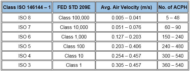
In addition, normally practiced air change rates for aseptic and non-aseptic areas are…

Air Change Rate Calculation
Consider a clean room of Class 100 generating nearly 50 particles per CFM with 99.9% HEPA efficiency. The air change rate is then calculated as:
V = g / (a-b)
where,
V = No. of Air Change Per Hour
g = rate of particle generation per cubic ft per hour
a = return air particulate concentration per cubic ft
b = supply air particulate concentration per cubic ft
Thus,
g = (50*60) converted to cubic ft per hour because we want to know air changes per hour
a = 100
b = 10 because HEPA efficiency is 99.9% i.e. (100-99.9)*100 = 10
Therefore, V = (50*60) / (100-10) = 33.33 = 33 ACPH
The equation and this example show that the ACPH is directly proportional to the rate of particle generation.
We need to adjust the airflow in two cases:
- If operating personnel present inside the room pose more chances of contamination
- If the room is idle and no activities are being performed.
To maintain cleanliness, the first case requires more airflow, the second the opposite. Using a steady airflow mechanism would waste energy in the second case.
Hence, pumps with Variable Frequency Drive (VFD) are recommended to dynamically supply the air as required.
Installation of Filters
When it comes to HVAC design, disregarding the filters can cross-contaminate the air, especially while dealing with finely powdered operations (< 2.5μ) such as tablet manufacturing.
We can’t deny the fact that particle sizes over 2.5μ play a vital role in contaminating the facility.
Therefore, filter selection and sizing become crucial aspects hereon. A common practice in HVAC system design is the installation of HEPA filters of 99.97% retention efficiency for a particle size range of 0.25 to 0.3μ.
The percentage of particles crossing through such filters is only 0.03%. For example, in the return line, air containing 10,000 particles per cubic ft or m when passed through the HEPA filter, only 3 particles are able to cross the filter and enter the room (10,000*0.0003=3).
ULPA filters have 99.9997% retention efficiency for the particle size of 0.10 to 0.12μ. Because they’re so minute and have fine efficiency, they’re recommended for Class 10 areas and applied in pharmaceutical industries in special cases.
The application of flange-type HEPA filters is common in pharmaceutical industries as they’re ideal for false ceiling mounting.
Below the filters, aluminum or SS-type grills are installed with an epoxy coating for easy cleaning and avoiding microbial growth downstream of the HEPA filter.
Prior to HEPA filters, pre-filters are used to restrict large-sized particles and reduce the load on the HEPA filters and increase their life. The pre-filter includes a bag-type filter of 10″ size.
Testing Filter Performance
The American Society of Heating, Refrigerating, and Air Conditioning Engineers (ASHRAE) developed standards viz. 52.1-1992 and 52.2-1999 classifying filters in terms of “Arrestance” and “Efficiency”.
The ability of a filter to capture dust and remove large-sized particles is called Arrestance.
Arrestance is expressed as:
μa = 1 – Ca / Cb
where,
μa – dust arrestance
Ca – Concentration of dust after filter
Cb – Concentration of dust before the filter
Evaluation of the filter’s ability to remove fine particles from air samples by upstream and downstream measurement of the particle concentration is called Efficiency.
Minimum Efficiency Reporting Value (MERV)
Measurement of filtration efficiency for different particle size-range rated as MERV. This value ranges between 1 and 16. The higher the MERV value, the more efficient the filter.
HEPA Filter Integrity Testing
These filters are tested using the DOP (Di-Octyl Phthalate) method. In this test, particle counting is performed upstream and downstream of the filter using any particle measuring device.
The test particles are prepared using condensation of DOP vapors having uniform 0.3μ size.
Now, as you saw earlier, we mentioned HEPA filter efficiency as 99.97% with an example of 10,000 particles upstream. In this case, the downstream particle count should not exceed 3 to serve the said efficiency.
Filter integrity testing is performed right before use called Pre-Use Post-Sterilization Integrity Testing (PUPSIT) and still has some reservations from the US.
This aspect needs to be the part of product batch release process.
Air Volume Systems
Basically, there are two types of air volume control systems.
- Constant Air Volume Systems
- Variable Air Volume Systems
Constant Air Volume Systems
A constant pressure gradient between the two areas is important for pharmaceutical manufacturing.
It is preferable to heat the air directly after the cooling coil in applications that require a more precise temperature and relative humidity control.
This ensures controlled humidity because of de-humidification in the cooling coils. The Constant Air Volume system also controls pressure for constant airflow.
Variable Air Volume Systems
These systems are employed in the admin section as the stringency to maintain the parameters is of less importance. Contrary to Constant Air systems, these systems save energy due to the absence of heating arrangement.
Validation of HVAC
Without qualification and validation, HVAC systems can’t be used for commercial manufacturing.
Validation provides documentary evidence that the system is designed, installed, and work as intended.
The activity begins with a protocol or strategy challenging each design aspect of the system.
All the documentary evidences such as RH, Temperature Mapping, Pressure Mapping, and other controlled parameters are recorded and archived. Also, all instrumentation calibrations are cross-checked prior to testing any parameters.
HVAC systems can be used for commercial manufacturing operations once PQ report is released.
Conclusion
Remember, high airflow and pressure can result in higher capacity for HVAC systems. It is the engineer’s responsibility to provide proper engineering solutions for design and implementation.
Maintaining sufficient differential pressure across the different classes of rooms is key to prevent product contamination.
All parts, sub-parts, instruments, and control devices must be properly monitored to avoid break-down issues. A periodic validation strategy should also be included in the Validation Master Plan.
Now I’d like to turn it over to you.
What factors you take into account while employing an HVAC system? Or may be you outsource everything? Either way, let me know in the quick comment below.



As I have already mentioned that I didn’t find any reference of recommended ACPH in ISO. Could you please help me to find the reference of ISO (Part/Version/Year) for same?
Here you go:
Previously it was ISO 14644-1:1999.
Now, ISO 14644-1:2015 is a published version, Edition 2
2015-12, “Cleanrooms and associated controlled environments — Part 1: Classification of air cleanliness by particle concentration”. This standard was last reviewed and confirmed in 2021. Therefore this version remains current.
Kindly refer this (you will have to purchase a copy of it).
Hope this clarifies your doubt.
Hi Saket,
I am trying to find the ACPH & velocity reference in ISO for all the class as you mentioned on table, however I didn’t find anything. Could you please let us know the reference of ISO (Part/Version/Year) for same?
Hi Surendra, the table you are talking about is a reflection of different standards compared side by side. You can cross check the latest ACPH values from ISO.
Thanks for sharing the valuable information regarding HVAC System Design.
Air changes per as per the chart shared by you is seems to be very high , It will increase the Size of AHU Blower , will result in Operating cost , Electricity consumption .
Since 10 years i am Executing Pharmaceuticals projects , Some companies follows
Grade-D NLT20 ACPH
Grade-C NLT40 ACPH
Grade-B NLT60 ACPH .
Please suggest..
Thanks Hariprasad, for commenting.
ACPH in the article above are the ISO standards. Values you have provided maybe followed by companies but they have to follow the ISO standards unless otherwise justifiable (special validation for deviating the standards, or establishing new standards or prove something of value, etc. etc.)
We are in discussion to design two units (same floor level 2)-drug product compounding room and aseptic filling room
Unit 1-non biological (pharma drug products including dental injectables)
Unit 2-biological (Non-live vaccines)
Please help me choose a best option
Option 1) have 3 AHUs that supplies to three sets of suits
i.e. AHS1 for U1 compounding and filling area,
AHS2 for U2 compounding and filling area,
AHS3 for supporting and general area.
Option 2) Have a single AHU for U1. U2 and supporting and general area.
AHS3 for supporting area
Hi Jaya! Thanks for giving me the opportunity to respond to your query.
According to the scenario you mentioned, Option (2) can lead to cross-contamination and the best suitable option is to keep different AHUs for different manufacturing areas with safe distance between them. So, I’d consider Option (1) over the another.
Kindly hit reply if you need any further info.
EU GMP required that laminar air velocity is 0.45±20%
Exactly Johnson! It comes around the range 0.36 to 0.54 m/s. I guess I have inserted an image table that I can’t edit. Now that you have commented, it’s a great source for others to update.
Understandably, commercial HVAC systems for establishments like pharma should produce clean and stronger airflow and pressure. I would imagine why this is so since these establishments run longer than a regular household. It takes a talented contractor to install efficient design solutions.
I am looking at a HEPA positive pressure system for a new 40 cubic meter clean room with a 10kPa above ambient air pressure. The room is to exhaust only, at a height of20m.
Unfortunately, the room does not have an external wall.
My question; is there a limit for the length of the exhaust pipe? Perhaps there is some kind of relay pump needed to work in addition to the main pump.
I remember being told, in a University that fume cupboards have an exhaust pipe limit on length on the way to the roof.
Thanks, Niall for your query. I guess you are talking about exhaust duct length here and not a pipe one.
One thing you need to keep in mind is that your pressure change (not pressure drop as we’re talking about relative pressure and not the absolute one) from return line to supply line is typically maintained less than 0.5 Inch of Water Column as a thumb rule to get good airflow. That’ll be your total pressure change across the AHU. This is because a blower will raise the air pressure at the supply point.
In addition, there is a concept called equivalent length while designing a duct system where Pressure Drop < Available Static Pressure. I'd highly recommend reading out this reference for additional details: https://www.cedengineering.com/userfiles/HVAC%20Design%20for%20Pharmaceutical%20Facilities%20R1.pdf
I hope this helps.